on
Notes on Isometric Projection
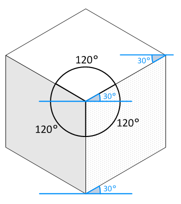
The concept of an isometric projection (from the Greek, ísos: “equal” and metrikós: “measure”), or simply: parallel perspective, had existed in a rough empirical form for centuries as a method for visually representing three-dimensional objects in two dimensions. The whole idea consists in keeping the three coordinate axes (x, y and z) equally foreshortened and making the angles between any two of them as 120 degrees.
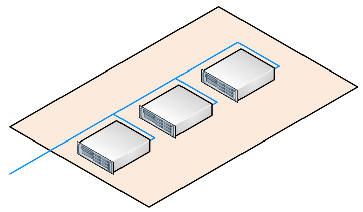
To project your drawing isometrically, let’s say: a generic computer network topology, all your elements (devices, cabling, surfaces, etc) must obey this rule and as a result you will end up with the following aspect:
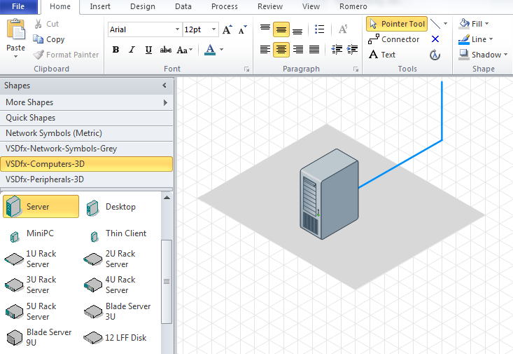
Many flavours of drawing tools are currently available in the market, I opted to embed Microsoft Visio in this discussion as it turned out to be considerably popular among Information Technology engineers. The easiest way to freely draw isometric elements is to use an isometric grid. An isometric grid can be described as an backgroud pattern of isometric shapes that can be used as a guide for your shapes and drawings. For example:

Unfortunately Microsoft Visio does not support such feature, which makes this article relevant for any tool you may use. Luckily you can easily find templates on-line containing an isometric grid as its background image, such as the ones found here.
If you have already been using Microsoft Visio for a while, you probably have notice that many downloadable shapes contains the words: 2D, 3D or isometric. 3D and isometric shapes are (mostly) the same when it comes to .vss files. They are the ones you will need in order to create three dimensional diagrams.
For the rest, all you need to do is to find the appropriate grid size, and start drawing on the top of it:
If keeping the grid is a problem, you can copy the created diagram by selecting all elements (CTRL+A) and pasting it into a blank template.